|
The Pad Chamber Geometry Database
|
The relevant geometry information for the pad chambers is stored in two Objectivity databases
(data only) as well as in an ASCII file (both data and simulation). The usage of ASCII files to
store things are not very popular in PHENIX, and will most likely be removed all together from the
reconstruction chains. However, they will still be used for transient storage before the
data is put to rest in Objectivity. The Objectivity macros mentioned below uses an ASCII file to
read the data that is to be put into the database.
The ASCII database
The ASCII file containing chamber positions and other parameters (cell spacings and
so on) is called padGeometry.txt. For the time being (run 2000 at least), a
special version of this file HAS to be used for simulated data files (set a soft
link to padGeometrySimulationNormal_IDOmod.txt), since this data is not yet stored in
the Objectivity database.
The file has the following structure:
NO_SECTORS_PC1 NO_SECTORS_PC2 NO_SECTORS_PC3
(1)
i.e. the number of sectors in PC1-3 respectively (16, 8, and 8).
PC ARM SECTOR
(2)
where PC is of course the PC number (0,1 or 2), while ARM = 0 means the east arm and
ARM = 1 is the west arm. SECTOR is in the interval [0,7] for PC1 and [0,3] for PC2/3.
For PC1, the coordinate triplet are as follows:
X0 Y0 Z0
X1 Y1 Z1
X2 Y2 Z2
X3 Y3 Z3
(3)
[(2) and (3) is repeated NO_SECTORS_PCX times for each chamber]
The coordinate triplets correspond to the defining points of the chamber corners,
p0, p1, p2 and p3, more
precisely the (outer) corners of the chamber wire planes (see Figures 1-4 below). The "inner"
corner points, close to z = 0, can only be used (as of April 2001) when the geometry is read from
the database.
NOTE: these numbers are surveyed after each arm move and thus the database (both
Objectivity and the ASCII file) need to be updated. Information on how to calculate these numbers
(and write out new padGeometry.txt files) can be found
here.
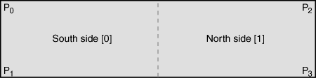
Figure 1. PC1E sector (two modules).
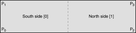
Figure 2. PC1W sector (two modules).
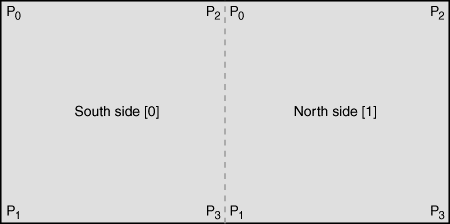
Figure 3. PC2/3E sector (four modules).
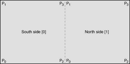
Figure 4. PC2/3W sector (four modules).
Last in the geometry file is a list of chamber parameters. These are in turn:
|
xOffset[0]
|
xOffset[1]
|
xOffset[2]
|
|
zOffset[0]
|
zOffset[1]
|
zOffset[2]
|
|
gasAtten[0]
|
gasAtten[1]
|
gasAtten[2]
|
|
anodeSpacing[0]
|
anodeSpacing[1]
|
anodeSpacing[2]
|
|
pixelLength[0]
|
pixelLength[1]
|
pixelLength[2]
|
|
sideWidth[0]
|
sideWidth[1]
|
sideWidth[2]
|
|
centerWidth[0]
|
centerWidth[1]
|
centerWidth[2]
|
|
pixelSpacing[0]
|
pixelSpacing[1]
|
pixelSpacing[2]
|
|
cellSpacing[0]
|
cellSpacing[1]
|
cellSpacing[2]
|
|
z0Gap[0]
|
z0Gap[1]
|
z0Gap[2]
|
|
nWiresPerSect[0]
|
nWiresPerSect[1]
|
nWiresPerSect[2]
|
|
nPadsAcrossWire[0]
|
nPadsAcrossWire[1]
|
nPadsAcrossWire[2]
|
|
nPadsAlongWire[0]
|
nPadsAlongWire[1]
|
nPadsAlongWire[2]
|
with the PC numbers given in the brackets. Most of these varibles are self explained. The offsets,
xOffset and zOffset, are the distances between the sector center points and the corner points. The
gas attenuation, gasAtten, should probably not be in this file to begin with.. The gaps, z0Gap,
are the distance between the chambers in each sector (in z). Since there is only one chamber per
sector in PC1, this variable is zero for this PC. In PC2/3 there is a discrepancy of several
centimeters in this variable between simulation (PISA) and the real surveyed positions (as of
April, 2001). For numbers, see the tail of the padGeometry.txt file.
The Objectivity database
Here comes the tricky part. The geometry data has been divided into two different database banks.
The chamber coordinates are stored in geom.pad.geocham, while the chamber parameters are
stored in geom.pad.geopar.
The variables stored (for each sector/module) in the chamber coordinate database
are as follows:
SouthDownPoint (p0)
SouthUpPoint (p1)
NorthDownPoint (p2)
NorthUpPoint (p3)
|
PC
Arm
Sector
Side
|
The variable names in the parameter database are similar (but not exactly the same) as the
variables in the ASCII database discussed above (for each PC):
PC
gasAtten
anodeSpacing
pixelLength
sidePixelWidth
centerPixelWidth
pixelSpacing
cellSpacing
nActiveSectors
nSectPerArm
nWiresPerSect
|
nPadsAcrossWire
nPadsAlongWire
z0Gap
xOffset
zOffset
pcRadius
phiBottomEast
phiTopEast
phiBottomWest
phiTopWest
|
The code for filling the database is kept in padDetectorGeo.cc (methods
padDetectorGeo::PutIntoGeoChamDatabase() and
padDetectorGeo::PutIntoGeoParDatabase()). To use these methods, there are two root macros
called putGeoChamIntoObjy.C and putGeoParIntoObjy.C in the
/direct/phenix+workarea/nilsson/objy/offline/database/data/final directory that does all the dirty
work for you (backup tar ball can be found here). To actually run
these macros, you probably first need to go through the
Objectivity tutorial and
set up the directories properly. You will also need a federation ID. First create a test database
that you fill with the help of the macros above. Then try to read out the information as well with
the reconstruction code (plot the chamber hits e.g.). Only when this works you may try to fill the
real database. NOTE: Use the correct TimeStamp when you fill/read from the database.
Paul Nilsson, April 24, 2001.
[Back]
|
|
|