AT90S8535 pin configuration
(package PLCC)
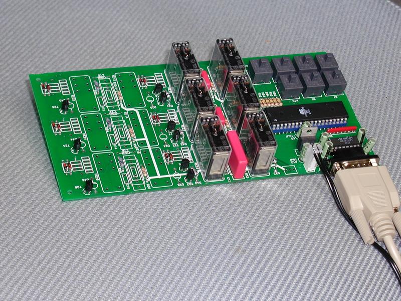
The tester is testing how well resistors can survive a HV (2kV) for a short moment. This is required in the TRT detector in the ATLAS experiment,where a broken wire may give a short pulse of 1.6kV through the reistors on the readout card placed on the detector itself.
Relays and capacitors are used to generate the short HV pulse. The voltage across the resistor is measured before and after the test. A CPU, an ATMEL processor (AT90S8535) , controls the test and onchip ADCs measures the voltage drop. A discharge is made repeteadly for several hours or day, with a discharge interval between 1 to 1000 seconds. Up to six resistors (R1 to R6) can be tested simultanously. A simple RS232 protocol is implemted for communication.
AT90S8535 pin configuration
(package PLCC)
| Mnemonic | Pin | Usage |
| PA0/ADC0 | 40 | ADC0 : Analog input R1 |
| PA1/ADC1 | 39 | ADC1 : Analog input R2 |
| PA2/ADC2 | 38 | ADC2 : Analog input R3 |
| PA3/ADC3 | 37 | ADC3 : Analog input R4 |
| PA4/ADC4 | 36 | ADC4 : Analog input R5 |
| PA5/ADC5 | 35 | ADC5 : Analog input R6 |
| PA6/ADC6 | 34 | not used |
| PA7/ADC7 | 33 | PA7 : Manual release R1-R6 - input |
| PB0/T0 | 1 | PB0 : Relay 1 R1 - output |
| PB1/T1 | 2 | PB1 : Relay 2 R1 - output |
| PB2/AIN0 | 3 | PB2 : Relay 1 R2 - output |
| PB3/AIN1 | 4 | PB3 : Relay 2 R2 - output |
| PB4/SS | 5 | PB4 : not used output |
| PB5/MOSI | 6 | MOSI : SPI output/Serial programming |
| PB6/MISO | 7 | MISO : SPI input/Serial programming |
| PB7/SCK | 8 | SCK : SPI clock/Serial programming |
| PC0 | 22 | PC0 : Relay 1 R3 - output |
| PC1 | 23 | PC1 : Relay 2 R3 - output |
| PC2 | 24 | PC2 : Relay 1 R4 - output |
| PC3 | 25 | PC3 : Relay 2 R4 - output |
| PC4 | 26 | PC4 : Relay 1 R5 - output |
| PC5 | 27 | PC5 : Relay 2 R5 - output |
| PC6/TOSC1 | 28 | PC6 : Relay 1 R6 - output |
| PC7/TOSC2 | 29 | PC7 : Relay 2 R6 - output |
| PD0/RXD | 14 | RXD : UART receive |
| PD1/TXD | 15 | TXD : UART transmit |
| PD2/INT0 | 16 | PD2 : Manual release R1 - input |
| PD3/INT1 | 17 | PD3 : Manual release R2 - input |
| PD4/OC1B | 18 | PD4 : Manual release R3 - input |
| PD5/OC1A | 19 | PD5 : Manual release R4 - input |
| PD6/ICP | 20 | PD6 : Manual release R5 - input |
| PD7/OC2 | 21 | PD7 : Manual release R6 - input |
Tested resistors
| Resistor | Test period | Discharge interval | Voltage before | Voltage after |